User's guide
This is the user manual for 2c8 Lite. It begins with descriptions of commonly used terms followed by a detailed walk through of the program and its functions.
The main purpose op 2c8 Lite is to create and maintain models. The models are stored locally on your computer or on a server shared by multiple users. This chapter describes some of the terms that are most commonly used throughout this manual.
| Model | A model is a graphic representation of some kind. It could describe for example a business process or an organisation. The model contains a set of symbols and relations between these that together makes up the content of the model. In addition to the visual content you can also connect describing texts and links to documents directly on the model. |
| Object | An object describes some kind of entity that can be a part of a model. It could be for example a business object, an activity or an individual. The available object types in a model depends on the type of model you are working with. |
| Symbol | When you place an object in a model it is represented by a symbol. All the object's data such as its title, description and documents belong to the object itself and will therefore be the same regardless of which model the object is shown in. The appearance of the symbol on the other hand can be changed without having the changes show in other models where the object is used. The symbol's size, position, color and font settings are all examples of settings that only affects the appearance of the symbol and not the object itself. |
3.1 Login
The login dialog is the first dialog that is shown when 2c8 Lite is started. Here you can either login and work on a 2c8 server or work offline.
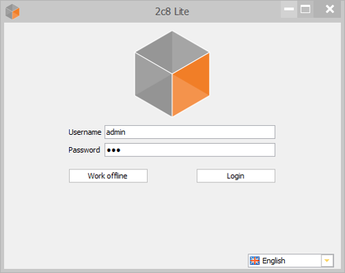
When you work online the models are stored on a 2c8 server where users from the same company or organization can share models. 2c8 Lite gives all users of the same server the ability to organize, share and cooperate with models. If you work offline the models are stored as files on your computer.
3.2 Dashboard
The dashboard in 2c8 Lite can be described as the users home screen. It is organized in a left panel, a top panel and a main panel that gives an overview of the models and tasks. The user interface is designed to keep the workflow in focus.
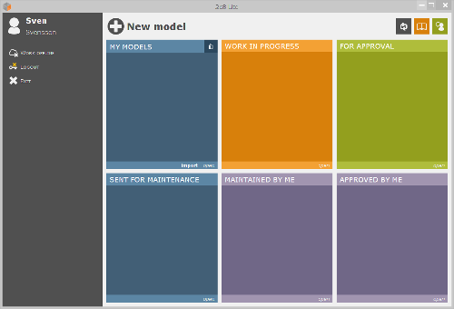
3.2.1 Left panel
From the left panel the user can access basic functions pertaining to the session. In the top of the left panel is an avatar followed by the users first and last name. By clicking on the avatar a dialog is shown where the password can be changed.
| Work offline | Changes from the current server session to working locally with files on the harddrive. |
| Log out | Ends the current server session and takes the user back to the login dialog. |
| Close | Closes the application. |
3.2.2 Top panel
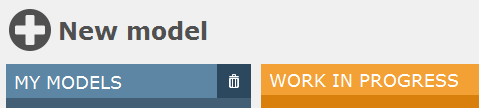
The top panel consists of a number of buttons with the following functions.
| New modell | Creates a new, empty model. |
| Reload | Reloads and updates the view. |
| Open manual | Opens the manual with the computers default PDF reader. |
| Support | Shows a dialog with contact and license information. |
3.2.3 Main panel
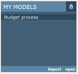
The main panel contains a matrix of six boxes where each box contains a list of models. The boxes represents different responsibilities the user has with respect to the models in the corresponding list. See the chapter Workflow states and Workflow responsibility for more information about the workflow.
| My models | Models with status "draft" created by the current user. |
| Work in progress | Models with status "New model" created by the current user. |
| For approval | Models with status "Editable model" or "Under revision" where the current user is the maintainer. |
| Sent for maintenance | Models where the current user is the maintainer. |
| Maintained by me | Models with status "Under revision" where the current user is the approver. |
| Approved by me | Models where the current user is the approver. |
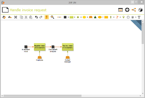
3.3 Modeling area
The modeling area is the part of the application where the model is edited.
See chapter Models for more information.
The main purpose of 2c8 Lite is to create and maintain models of the business. This chapter describes how to create and edit models in 2c8 Lite.
4.1 Create new model
Click on the button »New model« to create a new model. You can then choose which type of model to create. What model types to choose from depends on the application profile. When the model has been created it is automatically opened for editing.
4.2 Open model
To open an existing model select it an then click »open«. A model can also be opened by double clicking on it.
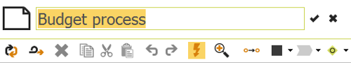
4.3 Change model name
To change a models name first open the model and then click on the model title above the model. The title then become editable.
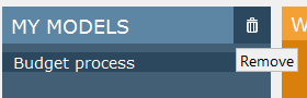
4.4 Remove model
To remove a model select it and click the »Remove« button.
4.5 Edit modell
When you open a model it is shown in the editing view. The editing view consists of a toolbar and a modeling area. The toolbar has buttons for common functions together with buttons for placing the available object types and relation types in the model. The modeling area shows the graphical representation of the model, consisting of symbols and relations between these.
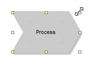
4.5.1 Add symbols
To create a new object and add it to the model you choose one of the object types from the toolbar and click somewhere in the model. You can also use the number buttons 0-9 on your keyboard to quickly choose a type based on its position in the toolbar. Pressing the same button multiple times will toggle between the available types within a group. When you have entered a title for the new object in the popup you click somewhere outside it or press »Enter«. The object is created and a new symbol is created for it and placed in the model.
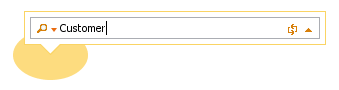
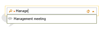
You can also add a new symbol for an existing object. Start by adding it the same way as a new object. When you start entering the title of the object you will get a list of objects matching this title. If you choose one of the objects in the list this object will be reused instead of creating a new one.
4.5.1.1 Snabbval
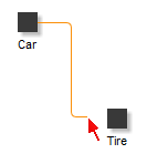
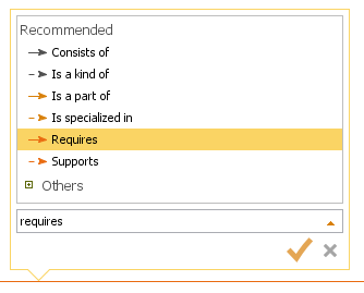
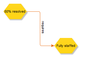
If »QuickDraw« has been enabled in the toolbar then there is a quicker way to build a model from its existing symbols. When you hover with the mouse above one of the symbols in the model you can see arrows appearing in the directions where the program has suggested relations available. Move the mouse above one of the arrows to see the suggested object types to place in this direction. When you click one of them and enter a title a new object of this type will be created.
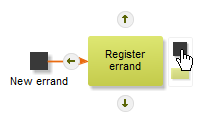
The new symbol is placed at a fixed distance from the source symbol in the correct direction and a new relation of the recommended type is created to it.
You can also use the keyboard shortcuts for Quickdraw. Use »Ctrl+arrow keys« to move the selection and then »Ctrl+Shift+arrow keys« to add a new symbol in a given direction. Press multiple times to toggle between the recommended types in that direction.
4.5.1.2 Add multiple symbols
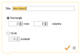
You can add multiple objects at once by choosing a type and then clicking and dragging across an area in the model. The popup that shows lets you enter a title and suggests how many symbols to place, based on the default size of the symbol type and the size of the area.
4.5.2 Add relations
To add a new relation between two symbols you choose »Relation (R)« in the toolbar and click the symbol you wish the relation to start from. You then click the other symbol to create the relation. You can also click the empty area of the model to control the way the relation takes by adding new control points.
You can create relations from one symbol to multiple others with one operation. Just click the »start« symbol and then click and drag around all the »end« symbols. The new relations will automatically get the recommended types.
4.5.3 Select symbols and relations
All editing of symbols and relations are based on the current selection. There is a number of ways to control which symbols and relations that are part of the current selection:
- Click on a symbol or relation to select this and deselect everything else.
- Drag around an area to select everything within it.
- Press »Shift« while selecting to add or remove symbols and relations to/from the selection.
- Use »Ctrl+arrow keys« to change selection based on direction in the model. This only works when a single symbol is selected.
- Use »Ctrl+A« to select everything.
- Click somewhere in the model to deselect everything.
4.5.4 Remove symbols and relations
To remove symbols and relations you select them and do one of the following:
- Click the »Remove« button in the toolbar.
- Right click the selection and choose »Remove«.
- Press »Delete« on the keyboard.
Note that only the symbols and relations will be removed and not the objects. You can add new symbols and relations using the same objects but you will loose any appearance settings that was made to the old symbols and relations.
4.5.5 Redigera symboler
This section covers the different ways you can edit a symbol in the model. Most settings affects only the symbol and not the underlying object, but some of them will affect the object as well and could thereby have effect on other models as well.
4.5.5.1 Size and position
To move a selection you drag it with the mouse. If you drag in one of the corners of the selection you will resize the symbols instead. You can also move the selection by using the arrow keys on the keyboard. Hold »Shift« down to move the selection one pixel at a time for finer control of the placement.
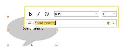
4.5.5.2 Title and font
To change the title of an object you can double click the symbol, right click it and choose »Edit label«, or use the keyboard shortcut »F2«. If you click the arrow at the right side of the title popup you can also change the font and color of the text. Note that the title is an object setting which will affect all models where the object is used, while the font settings will only affect the currently selected symbol.
A list of matching objects will be shown when you edit the title in the same way as when you add a new object. You can select an object in the list to switch to another object instead of renaming the current one. The old object will still exist and you can place a new symbol for it later in the current model or in another model.
To change the size and position of the label you press »Ctrl« on the keyboard and then position and resize it the same way you would a selected symbol.
4.5.5.3 Set default size
Each object type has a standard size. To reset symbols to their standard size you right click them and choose »Set default size«.
4.5.5.4 Center align label
The label of a symbol can be moved and resized independently of the symbol. By right clicking the symbol and choosing »Center align label« you can keep the text centered within the symbol. It will keep centered as long as you do not manually move or resize the label.
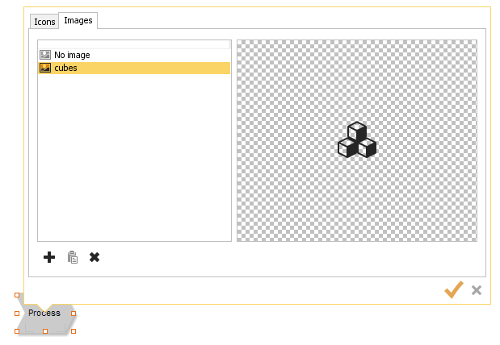
4.5.5.5 Image
If you wish to you can replace the default appearance of a symbol with an image. Right click the symbol and choose »Image«. In the popup shown you can see the images available in the repository. You can create new images by clicking the browse button or by dragging image files from the file explorer. You can also use the button for pasting from the clipboard if you have previously copied an image from somewhere else. When you have selected the image to use for the symbol you can use the »Set default size« function to set the correct size of the symbol based on the image size.
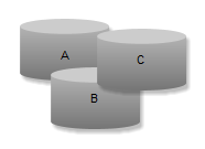
4.5.5.6 Order
When right clicking a symbol the sub menu »Order« contains options for controlling the depth order of selected symbols, i.e. the drawing order of the symbols. The figure below shows three symbols »A«, »B« and »C«. If you select »A« and choose »Move forward« the symbol will be placed between »B« and »C«. If you instead choose »Move to front« it will be placed above both of the other symbols. The options »Move backwards« and »Move to back« work in the same way but in the opposite direction.
4.5.5.7 Change object type
You can change the type of an object by right clicking it and choosing »Change object type...« or by using the keyboard shortcut »X«. This is a change of the object and will therefore affect all symbols which points to it.
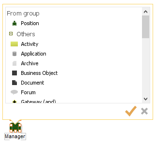
In the popup shown when changing the type you can see the types you can change to. At the top you can see the types within the same »group«, followed by all other types. In some cases such as in the example below with »individual« you only change between different alternative appearances of the same object type, i.e. the type is still »individual« but the appearance can be switched between a woman and a man.
4.5.6 Redigera relationer
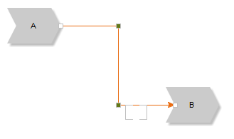
A relation is always drawn between two symbols and the appearance of the relation is determined by a number of control points placed along its path.
4.5.6.1 Control points
A relation is defined by its control points. The points divide the relation into one or more segments. Every time you select a relation you actually select a specific segment of the relation. You can then drag the segment with the mouse or move it with the arrow keys on the keyboard. If you move the first or last segment then new control points will automatically be created when needed.
You can also drag a single control point to move it. This will move both of the segments at that control point.
To align segments that are close to each other you can select the symbols that the relations are connected to and press »Space«.
4.5.6.2 Title and font
To edit the title of a relation you either double click the label, right click the relation and select »Edit label« or use the keyboard shortcut »F2«. If you click the arrow to the right in the popup shown you can also edit the font and text color of the relation label.
To edit the size and position of the label you press »Ctrl« and click the label. You can then change the size and position in the same way as for a symbol. If the relation does not have a title you can select the relation to see where the label is, it will be drawn as part of the selection.
4.5.6.3 Appearance
Under »Appearance« you can change the appearance of the relation by choosing line type, width and color.
4.5.6.4 Change relation type
To change the type of a relation you right click the relation and choose »Change relationship type...«. You can also use the keyboard shortcut »X«. The popup shown is the same that is used to edit the title but lets you choose type as well. The recommended types are shown at the top followed by all other types available in the model.
4.5.6.5 Reverse direction
By right clicking a relation and choosing »Reverse direction« you can reverse the direction of the relation, making it start in the current »end« symbol and end in the current »start« symbol.
4.5.6.6 Rotate label along relation
By toggling the »Rotate label along relation« option you can control how the text is laid out along the relation. If this option is active the text will be drawn vertically when close to vertical segments, otherwise it will always be drawn horizontally.
4.5.7 Align symbols
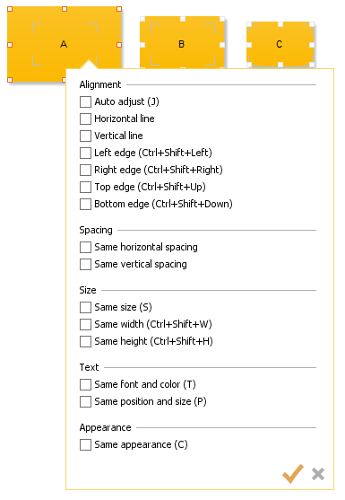
When you have selected multiple symbols you can right click the selection and choose »Align...« or use the shortcut »A«. The popup shown contains options that align the symbols in the selection in some way in reference to a »start« symbol. You can see which of the selected symbols is the start symbol on the color of the selection. Many of these alignment options also have keyboard shortcuts that are shown next to the options.
| Auto adjust | The application will try to adjust the position of the symbols according to their current position. If you place symbols in a somewhat straight horizontal line they will be adjusted to a straight line, and the same way for vertical lines. |
| Horizontal line | Places symbols with their center points on a horizontal line. |
| Vertical line | Places symbols with their center points on a vertical line. |
| Left edge | Places the left edges of the symbols along a vertical line. |
| Right edge | Places the right edges of the symbols along a vertical line. |
| Top edge | Places the top edges of the symbols along a horizontal line. |
| Bottom edge | Places the bottom edges of the symbols along a horizontal line. |
| Same horizontal spacing | Moves symbols that lie on a horizontal line so that the distance between each symbol is the same. |
| Same vertical spacing | Moves symbols that lie on a vertical line so that the distance between each symbol is the same. |
| Same size | Makes all symbols the same size. |
| Same width | Makes all symbols the same width |
| Same height | Makes all symbols the same height. |
| Same font and color | Makes all symbol labels the same font and text color. |
| Same position and size | Changes the position and size of the labels so that they all have the same position and size relative to their symbols. |
| Same appearance | Sets the same color and border settings on all symbols. |
4.5.8 Copy, cut and paste
The choices for copying, cutting and pasting are available both in the context menu and in the toolbar. You can also use the shortcuts »Ctrl+C«, »Ctrl+X« and »Ctrl+V«. When you paste copied or cut material into a model you create new symbols and relations pointing to the same objects. If you wish to create completely new copies (new objects) instead you can choose »Paste as copy« instead (»Ctrl+Shift+V«).
4.5.9 Text objects
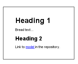
Text objects behaves somewhat differently from the other types and are used to show text in the model. When you create a text object you give it a title but it is not the title that is shown in the model but instead the object's description (see Descriptions). The description can contain formatted text, images and links to other objects and models.
4.5.10 Zoom
To zoom in or out in a model you press »Ctrl+Plus« or »Ctrl+Minus« on the keyboard or press »Ctrl« and use the mouse wheel. The model will zoom around the current location of the mouse pointer in the model. To reset the zoom level to 100% use the keyboard shortcut »Ctrl+0«. You can also use the zoom control in the toolbar to control the current zoom level.
4.5.11 Undo/redo
Most of the operations you make in the modeling editor can be undone and redone by using the »Undo« and »Redo« buttons in the toolbar or by using the shortcuts »Ctrl+Z« and »Ctrl+Y«.
4.5.12 Refresh model
The toolbar contains a button that refreshes the model from the data source. This is mostly useful in server environments where other users might have done changes since the model was last loaded. You can also use the keyboard shortcut »F5« to refresh the model.
4.6 Swimlane models
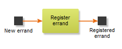
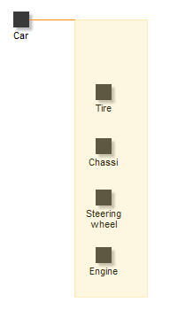
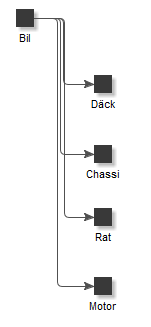
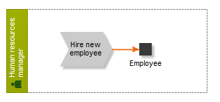
There is one standard model type that behaves differently from other models in 2c8 Modeling Tool and this is the swimlane model. In a swimlane model some object types are shown as »swimlanes«. When you create a new swimlane model you get to choose the object types that will be swimlanes and which types to automatically create relations to when symbols are placed within the swimlanes.
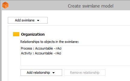
In the example above all positions will be drawn as swimlanes and if you place an activity or a process within the swimlane a relation of type »Accountable - RACI« will automatically be created from the swimlane to the activity/process. The relation will not be visible in the model but is equal to other relations in all other ways. It will be visible in the object properties and can be used to create lists etc.
4.7 Document links
2c8 Modeling Tools is not intended as a document management tool. Instead there is a function to create named links to documents in external document management tools, or on a shared network drive. It is also possible for third part plugins to work directly against an external system from inside the program to easily link documents to models or objects.
To create or edit document links right click on a symbol and choose »Documents« from the context menu. To edit document links connected to the model, right click on an empty part of the model and choose »Documents«.
4.8 Descriptions
Descriptions are longer, formatted texts connected to objects or models. To add or edit an object's description, right click on the symbol and choose »Description « from the context menu. To edit a model's description right click on an empty part of the model and choose »Description«.
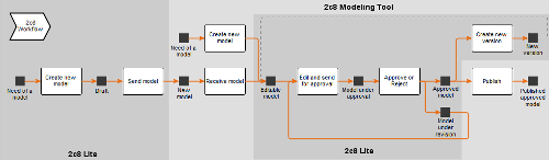
Workflow is used in 2c8 Modeling Tool to manage changes to models over time. It is a kind of revision management, a change process. The main activities when using the workflow engine is to assign maintainers and approvers to models in a repository, and then send models for approval or re-open approved models for editing. The process is described in the figure below. The following section explains the different states of this process and how the workflow cycle works.
5.1 Workflow states
The workflow contains six different states, where each state describes where in the workflow cycle a model is right now.
| Draft | Drafts are created by users of 2c8 Lite. In this state the model does not yet exist in a repository in 2c8 Modeling Tool. It might not yet have the correct model type and should be considered just a draft. You cannot create a draft in 2c8 Modeling Tool since models can only be created within a repository and with a given model type. |
| New model | A new model is a draft that has been sent for approval into a repository. Selected users of 2c8 Modeling Tool can then choose which repository to place the model in and assign it a model type, maintainer and approver. The difference between drafts and new models are that drafts are work material in 2c8 Lite while a new model indicates that the creator of the draft considers it done and wishes it to be added to a repository. |
| Editable model | In this state the model has been added to a repository and has been given a model type. All models created in 2c8 Modeling Tool are initially in this state as well. Models that have been approved and then re-opened for editing are also in this state. If you do not use workflow at all the models will remain in this state indefinitely. Models that were created in earlier versions of 2c8 Modeling Tool will also be in this state unless they were locked with the old revision management system, in which case they will be considered approved. |
| Under approval | In this state the model has been sent for approval by a maintainer. The model is no longer editable and awaits approval by the user designated as approver of the model. |
| Under revision | In this state the model has been sent for approval but has been rejected. This state is much the same as the editable state and is used to keep track of models that are considered done but has been rejected. If it should not be removed completely there is probably only some minor changes needed before re-sending it for approval. |
| Approved model | A model is approved when an approver decides that it correctly describes what is intended and decides to approve it. An approved model can not be edited, and if it is re-opened for editing a new version of the model is created for editing. |
The business objects shown in the chapter introduction are not all actual states in the workflow engine. They are a part of the process picture to facilitate understanding of the meaning of the activities. The objects »New version«, »Need for model« and »Published model« will never be shown as actual states of the model.
5.2 The workflow cycle
The workflow cycle is the process that moves models in a repository through the different state. The process starts either with an editable model created in 2c8 Modeling Tool or with a draft created in 2c8 Lite. For the parts of the workflow state that pertains to 2c8 Lite we refer to the manual for 2c8 Lite.
When a model is created in 2c8 Lite it starts in the state »Draft«. A »Drawer« (2c8 Lite user) can edit the model by changing relations, adding symbols, documents, descriptions etc. This happens under the activity »Send model« which is completed when the maintainer sends the model for approval. The model is then taken to the »New model« state and a new activity is started, where the responsibility is transfered to an user of 2c8 Modeling Tool.
The Activity »Receive model« includes a 2c8 Modeling Tool user to review a model to determine whether the model describes reality correct or not.There are two choices, either approve the model and move it to the state »Editable model«, or reject the model and move it back to the state »Draft«. In the latter case the model is sent back to the drawer who can make the appropriate changes before the model can be approved.
When a »draft« has been imported by a 2c8 Modeling Tool user and is in the state »Editable model«, a maintainer can edit the model by changing relations, add symbols, documents, descriptions and so on. This happens under the activity »Edit and send for approval« which ends when the maintainer sends the model for approval. The model are then taken to the state »Model under approval« and a new activity begins where the responsibility for the activity is transferred to an approver.
In the activity »Approve or reject« an approver reviews a model and decides whether to approve it. There are two choices, either approve the model and move it to the state »Approved model«, or reject the model and move it to the »Under revision« state. In the latter case the model is re-opened for editing and sent back to the maintainer who can make the appropriate changes before the model can be approved. An approved model is locked for editing and is now considered an accurate description of reality.
Approved models are moved through the workflow cycle in the activity »Create new version« which creates a new version of the model in the state »Editable model«. This new version will be set as the current version in the workspace but the older approved version of the model is still stored in the system.
5.3 Workflow responsibility
There are two areas of responsibility in the workflow cycle that applies to 2c8 Lite. The individuals responsible for making changes to models are called »Maintainers« and the individuals responsible for approving models are called »Approvers«.
5.4 Working with workflow
To move a model through the workflow cycle you use the »Workflow« button in the toolbar of the model editor.
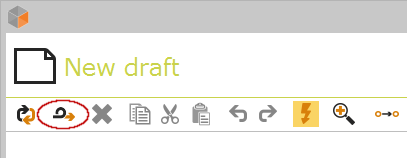
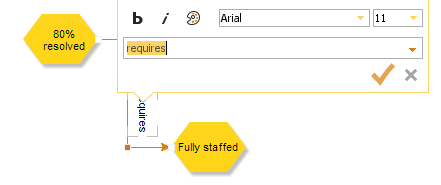
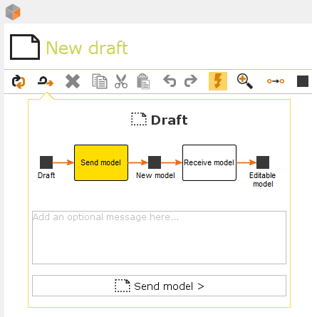
This opens a dialog that shows where in the workflow cycle the model is and one or more buttons for moving it to the next state. The dialog also shows the message from the user that made the last transition. To move the model to a new state add a message for the workflow log and click the appropriate button. In the figure below the only choice is »Send model« which takes the model to the »New model« state.
5.5 Which state is the model in?
To make the current state easily accessible the model has a small banner in the top-right corner with a color and an icon describing its current workflow state. You can also hover over the banner with the mouse to see the name of the state. This decoration is only shown in the editor and will not be included when publishing or exporting models. The following icons and colors are used.
![]() Draft (only visible in 2c8 Lite)
Draft (only visible in 2c8 Lite)
![]() Editable model
Editable model
![]() Under approval
Under approval
![]() Under revision
Under revision
![]() Approved model
Approved model
If the user has insufficient permissions to edit the model this is shown with a lock icon in the same part of the user interface. This is shown regardless of the current state of the model.
![]() Insufficient permissions for editing
Insufficient permissions for editing
This information can be used to see if the model is currently editable. If the color is orange and missing a lock icon then it can be edited. If the color is green or showing the lock icon it is not editable. (In 2c8 Lite it is also editable in the draft (blue) state).